
Visit the whole site at: https://borg20011.tripod.com/borg_link_o_rama.htm
Page 17.
Running lights signals in headlamps
(Understanding of a relay)
As requested. I made up a couple images for
layout. I figure instead of just telling the people how to wire it. Why not
explain how relays work.
Disclaimer: My knowledge of relays come from DIY Car Audio install. Just what I
have learned from installing amps with other devices off remote wires. Wiring
alarms.
Now - on to the relays.
There are two types of relays that are commonly used in 12-volt applications:
Single-pole Double Throw (SPDT) relays, which have 5 pins, and Single Pole,
Single Throw (SPST) relays, which have 4 pins.
Better off just getting the Double Throw relays. Single Throw relays usually
work fine for switches. On the Double Throw, as mentioned above, there is 5
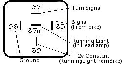
prongs. 85, 86, 87, 87A, and 30.
What are all the terminals? Look at attached image and try to see if you figure
it out yourself.
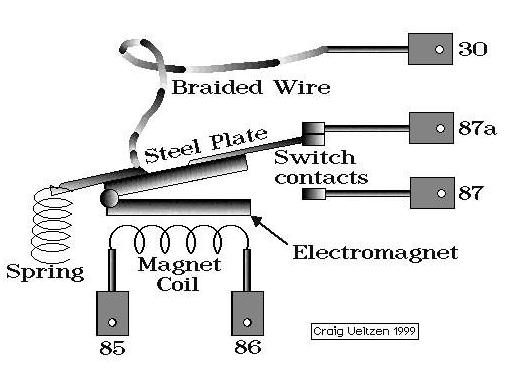
Confusing? Hopefully not. Lets break it down
some.
85 - relay coil can be either positive or negative but must obviously be
opposite 86
86 - Relay coil can be either Negative or Positive.
87 - has power when the Relay coil (85 and 86)is energized. Polarity is based on
what current you have on Terminal 30.
87A - Receives power from Terminal 30 When relay coil is not energized.
30 - +12volts if you want to trigger +12volts or Ground if Your Using the relay
to ground something.
So look at the picture. See what makes it switch?
So say you want to keep your stock running
lights in your headlight and you want to make them act as signals, without
losing the running light feature.
This is easy to do. You can set up the relay to make the headlight running
lights stay on. How is this done?
That is simple. You have 3 wires coming into your stock blinkers. If you replace
them with Gregg's (or any other single element flush mount). One is ground, One
is Signal lights (12v switched) and the other is running light (12v Constant).
You wire up the 12v constant to the relay. Ground everything. Again 85 and 86
are the pole switches. So hook up the signal light wire from the bike to the
relay - lets choose 85. Ground the relay to 86. Our 12v constant should go into
the relay into 30.
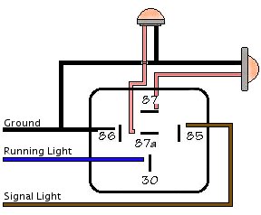
Now - where does this put us? 85 and 86 are grounded. The relay is not
energized. Which means in this mode 87a is constant. Plug in your running light
in the headlight to 87A.
Now when you put on your signal light. You'll see the running light in the
headlight flashing. What it is doing is turning off/on with the signal light.
How do you make the flush mounts flash now? We have 87 left over - in which is
switching between 87a/87 because 85/86 are energizing. 87 and 87a are going
on/off one after another.
This in results makes your flashers blink in opposite of one another.
Look at this chart for the wiring.
You will definitely need to get a good
flasher relay. I had this setup on my R6 with the stock blinker relay. Because
the Bosch relay has such low resistance - it'll blink fast.
I recommend the Libertek flash relay. It is adjustable and works the best with
the aftermarket LED lights.
I recommend using quick disconnect plugs on each wire from the Bosch relay to
the lights. That way you can take off your fairings and not have to worry about
disconnecting all the of the relay or what not.
Final wiring drawing.
All that courtesy of Corny on the http://www.r1-forum.com